A tandem press line running automotive body panels stamps six dies in sequence. Between each press, a part must move from one die to the next — aligned within 0.5 mm, arriving within a 200-millisecond window, 12 times per minute, for 20 hours a day. Two fundamentally different automation architectures handle this transfer: an overhead crossbar system mounted above the press line, or individual floor-mounted 6-axis robots stationed between presses. They look nothing alike, they cost differently, and they optimize for opposing operational priorities.
How Overhead Crossbar Automation Works
An overhead crossbar system spans the length of the press line — typically 30 to 60 meters for a five-to-six-press tandem line. A lightweight beam (the crossbar) rides on rails above the presses, carrying vacuum cups or mechanical grippers. The crossbar drops into each open die, picks the formed panel, lifts, travels horizontally to the next press, lowers into the die, and releases — all synchronized to the press crankshaft angle so that motion completes before the die closes. The entire line runs on a single electronic line shaft: one virtual master axis coordinates every crossbar and every press slide.
The defining metric is strokes per minute (SPM). A well-tuned overhead crossbar line on automotive outer body panels runs 12–18 SPM. The crossbar moves all parts simultaneously — when the bar lifts, every part between every press moves forward one station in a single coordinated stroke. This is the fastest way to move stampings through a tandem line.
How Floor-Mounted Tending Robots Work
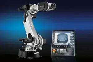
A floor-mounted tending robot is a 6-axis industrial robot positioned between two presses. It reaches into the upstream press to extract the part, rotates, and places it into the downstream die. A five-press line uses four robots. Each robot runs its own program, triggered by press-position signals from the adjacent presses. There is no mechanical link between stations — the robots coordinate over a real-time fieldbus.
Cycle time depends on part weight and robot reach. A 165 kg payload robot on a 2.5-meter reach moving a 15 kg door inner panel achieves 8–10 parts per minute. This is slower than a crossbar — each robot works alone rather than in lockstep — but the independence is the point.
Part Size, Weight, and the Physical Limits
- Overhead crossbar
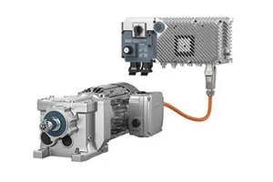
- Handles panels up to 4 × 2 meters and 40 kg per part. Tooling (vacuum cups or gripper fingers) rides on the crossbar beam. Total moving mass — beam plus all tooling plus all parts — can exceed 800 kg, driven by large servo motors or linear motors. The Y-3023-2-H00AA high-torque servo represents the class of drive needed for crossbar beam acceleration.
- Floor robot
- Payload ratings from 100 kg to 300 kg cover most stamping applications. Part geometry limits are reach-dependent — a 2.8-meter reach robot handles panels up to roughly 1.8 meters on the longest axis before the panel interferes with the robot's own structure during rotation. Floor-mounted layouts allow robots on both sides of the press line for large parts that need two-handed extraction.
Die Change: The Real Decision Driver
Overhead crossbar tooling is die-specific. Each set of vacuum cups and gripper fingers is machined to match one panel contour. When the die set changes — for a new vehicle model, a different panel, or a batch-size changeover — the crossbar tooling also changes. Tooling changeover on a five-press crossbar line takes 45–90 minutes, even with quick-change couplings. The crossbar beam itself may need to be swapped if the panel pitch (distance between press centerlines) changes.
A floor-mounted robot changes over in software. The mechanical gripper may change — a quick-change wrist coupling swaps end effectors in under 30 seconds — but the robot itself stays. The new recipe downloads from the cell controller: new path points, new I/O mapping, new interlock logic. A five-press robot-tended line can change over in 10–15 minutes if the grippers use a common quick-change interface.
If your press line runs three or more die changes per shift, floor robots pay back their slower cycle time in reduced changeover downtime. At one die change per day, the crossbar's speed advantage dominates the annual throughput calculation.
The rule of thumb in press line automation: overhead crossbars optimize for speed at low mix, floor robots optimize for agility at high mix. The crossover point is roughly two die changes per shift — above that, the changeover time saved by robots outweighs the per-part cycle time advantage of the crossbar.
How do I compare total cost of ownership between the two architectures?
Crossbar: higher initial capital (the beam structure, linear motors or large servos, and custom tooling for each die set), lower per-part labor and energy cost when running, but high tooling inventory cost (one set of crossbar tooling per die set). Floor robots: lower initial structure cost, higher per-part cycle time (more labor hours per 1,000 parts), near-zero tooling changeover cost, and the robots can be redeployed to other lines when the press line retools for a new product. For a line running 500,000 parts per year with one die change per day, the crossbar typically pays back its premium in 18–24 months. At 10 die changes per shift, the robot architecture wins on TCO from day one.
What about the press itself — does the automation choice constrain my press selection?
Yes. Overhead crossbar systems require presses with sufficient die-open height to accommodate the crossbar beam passing through. Typically this means an additional 300–500 mm of shut height beyond what the part and die alone require. Crossbars also need the press crown structure to support beam rails or guide tracks — not all presses are designed for overhead rail mounting. Floor robots only need clearance beside the press for the robot base, making them compatible with a wider range of press designs, including older mechanical presses retrofitted for automation. The servo drive selection also differs — crossbar beams demand high-inertia servo motors, while floor robots use lower-inertia motors optimized for rapid directional changes at the wrist.