A traditional coordinate measuring machine sits in a climate-controlled metrology lab on a 2-ton granite base, isolated from shop-floor vibration by pneumatic isolators. A ruby-tipped touch probe moves along three orthogonal axes, touching a machined part at 50 programmed points, recording each XYZ coordinate to ±1.5 microns — plus 2.5 microns per meter of travel. The inspection report is metrologically defensible, traceable to NIST, and takes 45 minutes per part. On the shop floor, an operator holds a structured-light optical CMM — essentially a 3D scanner with metrology-grade calibration — and captures 2 million points across the same part in 15 seconds. The optical CMM accuracy is ±15 microns — roughly 10 times worse than the traditional CMM — but it inspects 100% of the visible surface instead of 50 sampled points, and it does it next to the machine tool, not across the building. This article compares the two CMM technologies on accuracy, surface coverage, speed, and shop-floor suitability — so you can decide which inspection tasks belong in the lab and which belong at the point of production.
How Each Technology Measures
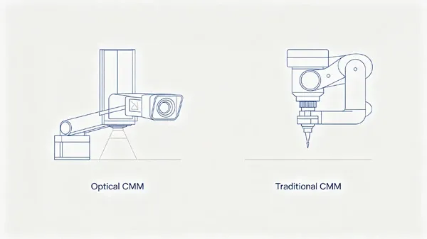
A traditional CMM is a contact measurement system. A probe — either a touch-trigger probe that records a point each time it contacts the surface, or a scanning probe that drags continuously across the surface recording points at up to 500 Hz — is mounted on a three-axis gantry, bridge, or articulated arm. Linear encoders on each axis measure probe position to sub-micron resolution. The CMM measures one point at a time, and each point is accurate because the machine's kinematic chain — granite base, air bearings, precision ground leadscrews — is designed to be orders of magnitude stiffer and more thermally stable than the part being measured.
An optical CMM is a non-contact measurement system based on structured light, laser triangulation, or photogrammetry. A structured-light optical CMM projects a pattern of blue or white LED light — typically a fringe pattern or random speckle pattern — onto the part surface and captures it with one or two calibrated cameras. From the distortion of the projected pattern as seen by the cameras, the system computes 3D coordinates for every pixel in the camera field of view simultaneously — producing 1 to 5 million points per frame. Accuracy is achieved through calibration to a certified artifact (a traceable sphere or length bar) and volumetric compensation that models and corrects for the scanner's thermal drift, lens distortion, and triangulation geometry errors.
Accuracy: When 10x Worse Is Good Enough
A traditional bridge CMM in a temperature-controlled lab (±1°C) delivers volumetric accuracy of ±1.5 to 3.0 µm + L/300 mm (where L is the measured length). For a 200 mm part, that is roughly ±2 to 4 µm. An optical CMM on the shop floor — where temperature swings of ±5°C over a shift are common — delivers volumetric accuracy of ±10 to 25 µm on a well-prepared matte surface. The accuracy gap is real: roughly 5 to 10 times worse for the optical system.
But accuracy is not the only measure of inspection quality. A traditional CMM samples 20 to 100 discrete points to characterize a part feature — a bore diameter measured at three cross-sections with 8 points each is 24 points total. If the bore has a 0.5 mm gouge from a broken tool insert that falls between the sampled cross-sections, the CMM report shows a compliant part. The optical CMM captures the entire bore surface at 50 to 100 points per square millimeter — 50,000 to 200,000 points total — and the gouge is impossible to miss. The optical CMM trades per-point accuracy for surface coverage, and for finding localized defects — dents, scratches, porosity, tool marks — coverage wins.
How much faster is optical CMM inspection?
The cycle-time comparison depends on how many features need measurement. For a part with 10 geometric dimensioning and tolerancing (GD&T) callouts — diameters, positions, flatness, parallelism — a traditional CMM program touches 80 to 120 points and runs in 8 to 15 minutes. An optical CMM captures the full part surface in 10 to 30 seconds; the GD&T evaluation takes another 30 to 60 seconds of computation. Total cycle time: roughly 1 to 2 minutes for the optical system versus 8 to 15 minutes for the traditional CMM — a 5 to 10x speed advantage.
But setup time can flip this comparison. A traditional CMM requires the operator to load the part onto the granite table, align it (either by fixture or by probing a datum reference frame), and launch the program — 2 to 5 minutes total. An optical CMM on a part that has shiny, machined surfaces may require 5 to 10 minutes of surface preparation — applying matting spray, allowing it to dry, removing it after inspection — which erases the cycle-time advantage. For matte, as-cast, or injection-molded parts that require no surface prep, the optical advantage is real and large. For shiny machined parts, the traditional CMM is often faster door-to-door.
What can an optical CMM NOT measure?
Optical CMMs have fundamental limitations that contact CMMs do not. An optical system measures what it can see — line of sight to the cameras is required. Internal features — a counterbore deep inside a housing, a cross-hole intersecting a main bore at a shallow angle, a threaded hole's minor diameter — are invisible to optical triangulation. A traditional CMM with a star probe or a right-angle probe styli reaches internal features that optical systems simply cannot access. Deep, narrow features with aspect ratios greater than 3:1 (depth to diameter) are optical no-go zones — the projected light cannot reach the bottom, and the camera cannot see it.
Optical CMMs also struggle with transparent, translucent, or highly specular surfaces — glass, clear plastic, polished carbide, mirror-finish molded surfaces. The projected pattern passes through or reflects away from the cameras. Contact CMMs have no such limitation — the probe touches whatever surface is there, regardless of optical properties. For parts with a mix of accessible external features and difficult internal geometry, a hybrid approach — optical for external surfaces, contact probing for internal features — is increasingly common on the shop floor, facilitated by multi-sensor CMMs that combine a touch probe and an optical scanner on the same machine frame.
Where on the shop floor does optical CMM work?
The value proposition of optical CMM is moving inspection from the lab to the point of production — inspecting a part while it is still in the machine tool or immediately after unclamping, so that any dimensional drift is detected within one part cycle, not one shift later when the lab report comes back. This works when the shop-floor environment is compatible with optical metrology:
- Ambient light control: strong sunlight through a loading-dock door or an overhead LED floodlight aimed at the scanning volume can wash out the projected pattern. Enclose the scanning station with curtains or a booth, or use a scanner with narrow-band blue LED projection and a matching bandpass filter on the camera — this rejects most ambient light.
- Thermal stability: optical CMMs have thermal drift compensation, but a 10°C temperature swing over a shift still produces 5 to 15 µm of measurement drift on a 500 mm part. If tolerances are tighter than ±25 µm, the optical CMM needs a temperature-controlled enclosure — at which point the "shop-floor" advantage blurs into "a smaller, cheaper metrology lab."
- Vibration: optical CMMs capture data in milliseconds — far less susceptible to intermittent vibration than a touch CMM that requires physical contact stability during probing. But persistent high-frequency vibration from a stamping press 10 meters away can blur the projected pattern. Mount the scanner on a passive vibration isolation pad or — better — position the scanning station away from impact machinery.
How to decide: Lab CMM or shop-floor optical?
| Factor | Traditional CMM (Lab) | Optical CMM (Shop Floor) |
|---|---|---|
| Volumetric accuracy | ±1.5–3 µm | ±10–25 µm |
| Surface coverage | 20–200 discrete points per feature | 1–5 million points covering entire visible surface |
| Internal feature access | Yes — with appropriate probe styli | No — requires line of sight |
| Inspection cycle time (10 GD&T callouts) | 8–15 minutes | 1–2 minutes (matte surfaces) |
| Surface prep required | None | Shiny/machined surfaces require matting spray |
| Shop-floor tolerance to ±5°C | Poor — accuracy degrades rapidly | Moderate — thermal compensation helps, but drift is measurable |
| Cost | $80k–250k + climate-controlled lab | $40k–120k, usable at point of production |
The optical CMM is not replacing the traditional CMM in the metrology lab — it is extending CMM-grade measurement capability to the shop floor for parts and tolerances where 15 µm is acceptable and 100% surface coverage is more valuable than 2 µm per-point accuracy. The decision is not which CMM to buy — it is which inspection tasks to move from the lab to the point of production, and which to keep on the granite table.