An extractive continuous emissions monitoring system pulls flue gas through a heated probe, sends it down a temperature-controlled sample line, strips the moisture in a condenser, and measures the oxygen content of what remains. The number it reports is not the oxygen value inside your stack. It is the oxygen value of a cooled, dried, and transported sample — which may have lost oxygen to condensate dissolution in the chiller, adsorbed onto the walls of a long sample line, or been altered by a leak at any of a dozen fittings between the probe tip and the analyzer cell. An in-situ zirconia analyzer eliminates the entire sampling chain. It mounts directly in the flue gas duct and measures oxygen at the process point — hot, wet, and in real time — using a ceramic electrochemical cell that generates its own voltage in proportion to the oxygen partial pressure difference between the process gas and a reference air stream. This is the physics behind that measurement, centered on the MRU OMS 420.
How a Zirconia Cell Turns Oxygen Concentration into Voltage
The sensing element is a thimble-shaped or disc-shaped ceramic made of zirconium dioxide (ZrO₂) stabilized with yttria (Y₂O₃). The yttria dopant creates oxygen vacancies in the crystal lattice — empty sites where an oxygen ion can occupy. When the ceramic is heated above 600°C, these vacancies become mobile and the material becomes an oxygen-ion conductor: a solid electrolyte. Coat both sides of the ceramic with porous platinum electrodes, expose one side to the process flue gas and the other to ambient reference air (which contains a known 20.95% oxygen), and the cell becomes an oxygen concentration cell governed by the Nernst equation:
E = (RT / 4F) × ln(Pref / Pmeas)
E is the cell voltage, R the universal gas constant, T the absolute temperature of the cell, F Faraday's constant, and Pref and Pmeas are the oxygen partial pressures on the reference and measurement sides. Because the relationship is logarithmic, the cell is naturally more sensitive at low oxygen concentrations — exactly where combustion tuning matters. A change from 1% to 2% O₂ produces a much larger voltage shift than a change from 19% to 20%, so the zirconia cell delivers its best resolution in the 0–10% O₂ range where boiler excess air control operates.
Three conditions must hold for the measurement to be accurate: the cell temperature must be constant (the OMS 420 regulates its internal heater to maintain the zirconia disc at a tightly controlled setpoint, typically around 700°C), the reference air on the inner electrode must be clean and dry (instrument air at 20.95% O₂, fed through a desiccant filter to prevent humidity from diluting the reference oxygen partial pressure), and the process side of the cell must see a representative flow of flue gas — not a stagnant pocket trapped behind a baffle or an eddy zone downstream of a duct bend.
In-Situ vs. Extractive: What You Gain and What You Trade
An extractive system's sample path — probe, heated line, condenser, pump, analyzer cell — introduces transport delay, potential leaks, and water-vapor interference. An in-situ zirconia probe eliminates all four at once, but it places the sensor directly in the process environment, where it must survive temperature, particulates, and corrosive gases without the protection of a conditioned sample.
- Response time
- In-situ: the zirconia cell responds to an O₂ change in under 5 seconds. Extractive: the gas transport time through the sample line plus the cell flush time typically adds up to 30–90 seconds. For closed-loop combustion control where the air-to-fuel ratio adjusts in real time, a 90-second measurement lag means the controller is always correcting for a condition that existed a minute and a half ago.
- Water vapor handling
- In-situ measures oxygen on a wet basis — the O₂ partial pressure in the actual gas mixture including water vapor. Extractive systems condense out the water before the analyzer, reporting oxygen on a dry basis. Wet-basis O₂ is lower than dry-basis O₂ by roughly 1–2 percentage points, depending on the fuel's hydrogen content. If the regulatory permit specifies dry-basis reporting, the OMS 420 converter applies a fuel-factor correction to calculate dry-basis O₂ from the wet measurement.
- Maintenance burden
- In-situ: the primary maintenance task is sensor replacement or cleaning, typically every 1–2 years depending on fuel and dust loading. No pump diaphragms, no condenser filters, no heated-line integrity checks. Extractive: weekly or monthly checks on the sample pump, condenser drain, line temperature, and leak-tightness — plus the same sensor maintenance. Over a 5-year lifecycle, the in-situ approach eliminates roughly 70% of the preventive maintenance tasks that an extractive system accumulates.
- Calibration access
- Extractive: you can flow calibration gas through the entire sample path, verifying the probe, line, condenser, and analyzer together. In-situ: you calibrate at the probe head by flowing test gas across the process side of the zirconia disc through a dedicated calibration port. The OMS 420 includes this port — connect a cylinder of certified O₂/N₂ mixture and verify the reading without removing the probe from the duct.
MRU OMS 420: Probe Design and Specifications
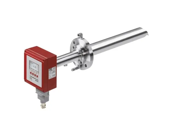
The MRU OMS 420 packages the zirconia cell, heater, and signal electronics inside a stainless steel probe designed for direct flange mounting into the flue gas duct. The probe insertion length determines how deep the sensor tip penetrates into the gas stream — and that depth determines whether the measurement represents the actual O₂ concentration or a stratified layer near the duct wall.
- Measurement range
- 0–21% O₂ standard; 0–100% O₂ option for oxygen-enriched combustion processes
- COe (CO equivalent)
- Optional second channel measuring unburned combustibles as a CO-equivalent concentration — detects incomplete combustion before CO emissions exceed permit limits. The COe sensor is a separate heated semiconductor element integrated into the same probe body.
- Probe lengths
- 300 mm, 500 mm, 800 mm, and 1000 mm — select so the sensor tip sits within the center third of the duct cross-section
- Process flange
- DN65 PN6 (standard) or ANSI 4-inch 150 lb
- Process temperature range
- Up to 600°C at the probe tip; the internal heater maintains the zirconia cell at its controlled setpoint independent of flue gas temperature within the rated range
- Outputs
- 2 × 4–20 mA (O₂ and COe), optional HART or RS-485 Modbus
- Housing
- IP65 die-cast aluminum with stainless steel probe tube
For natural gas combustion with consistent fuel quality, the single-channel O₂ version covers the need — excess air control uses only the oxygen reading to maintain the target air-to-fuel ratio. If the fuel composition varies — landfill gas, biogas, or mixed industrial off-gas — the COe channel adds a second dimension: it detects the combustibles spike that precedes a CO breakthrough, even if the O₂ reading has not yet dropped below the control setpoint.
Installation Rules That Prevent Bad Readings
The zirconia cell measures whatever oxygen partial pressure exists at the probe tip. If the tip sits in a stagnant flow zone where the gas composition differs from the bulk stream, the analyzer reports a number — but that number is wrong.
Insertion depth. The probe tip should penetrate into the center third of the duct. For a circular duct of diameter D, the center third spans from D/3 to 2D/3 from the insertion wall. A probe too short samples gas near the wall, where temperature is lower and oxygen may stratify — especially in horizontal ducts after a bend where the hotter core gas shifts to one side.
Distance from disturbances. Install the probe at least 2 duct diameters downstream of any bend, damper, or cross-sectional change, and at least 1 duct diameter upstream of the next disturbance. A flow disturbance downstream of a bend creates asymmetric velocity and concentration profiles that can persist for 5 diameters in a smooth duct. If the available straight run is short, select the longest insertion probe and aim for the geometric center of the duct.
Probe orientation. In a horizontal duct, mount the probe horizontally or at a slight downward angle — 5 to 10 degrees below horizontal. This prevents condensation from pooling on the sensor tip during cold start-up: even though the cell operates at 700°C, the cooler outer probe sheath can collect acidic droplets if oriented upward. In a vertical duct with upward flow, horizontal mounting is standard.
Reference air supply. The OMS 420 draws reference air through a small port on the probe housing. This port must receive clean, dry instrument air — if the ambient air around the probe is contaminated with fugitive flue gas or high humidity, the reference oxygen partial pressure shifts away from 20.95%, and the Nernst equation produces a proportional measurement error. An instrument-air purge at 0.5–1.0 L/min through the reference port is standard practice for permanent installations.
Where In-Situ Wins — and Where It Does Not
The in-situ zirconia approach is not universally superior to extractive analysis. It wins in specific scenarios and should be avoided in others:
In-situ excels at: natural-gas-fired boilers and furnaces with clean-burning fuel (low particulate, low SO₂), combustion optimization loops that need sub-5-second O₂ response, stacks where the cost of a heated sample line and analyzer shelter exceeds the cost of the analyzer itself, and plants where maintenance staffing does not support weekly extractive system checks.
Extractive remains the better choice for: fuels with high particulate loading that would coat a zirconia cell within days (biomass, coal without upstream particulate filtration), applications requiring simultaneous measurement of O₂, CO, NOₓ, and SO₂ from a single sample point (a multi-gas extractive analyzer covers this; the in-situ probe measures O₂ and optionally COe), and stacks where the probe insertion point is physically inaccessible for the annual sensor swap — an extractive system lets you put the analyzer at ground level while the probe stays in the stack.
For a broader selection of oxygen analyzer technologies — zirconia, electrochemical, paramagnetic, and optical, from portable handhelds to fixed CEMS — the category page covers the full range. If the monitoring scope extends beyond oxygen to CO, NOₓ, SO₂, and other combustion products, the gas analyzer category includes multi-gas extractive systems that complement an in-situ O₂ probe. For general water and gas analytical instrumentation — pH, conductivity, turbidity, dissolved oxygen, and the analyzer families that service environmental compliance beyond combustion — the analytical instruments category provides the cross-technology overview.
What temperature must the zirconia cell maintain for accurate measurement?
The yttria-stabilized zirconia ceramic becomes an oxygen-ion conductor above approximately 600°C. Below this temperature, the ionic conductivity drops exponentially and the cell output becomes unreliable. The MRU OMS 420 maintains the zirconia cell at approximately 700°C using an internal resistance heater with closed-loop thermocouple control. This temperature is high enough to ensure fast ionic conduction and a strong Nernst voltage, but low enough to avoid sintering the platinum electrodes over the sensor's service life. The heater and control loop compensate for flue gas temperature variations from ambient start-up to 600°C continuous operation.
How often does the zirconia sensor need replacement in a natural-gas boiler?
In clean natural gas combustion — the most benign environment for a zirconia cell — the sensor typically lasts 2–3 years before the cell impedance rises enough to degrade accuracy. In light oil firing, the service life shortens to 1–2 years due to trace vanadium and sulfur compounds that slowly poison the platinum electrodes. In biomass, coal, or heavy fuel oil, the sensor may need replacement every 6–12 months unless protected by a sintered metal filter that blocks the bulk of the particulate. The OMS 420 diagnostic output includes a cell impedance reading — when impedance doubles from the commissioning baseline, schedule a replacement before the reading drifts out of tolerance.
Can I calibrate an in-situ zirconia analyzer without removing the probe from the stack?
Yes. The OMS 420 probe head includes a calibration gas inlet port. Connect a cylinder of certified calibration gas — typically 2% or 5% O₂ in N₂ — to the port, flow at the specified rate (1–2 L/min), and wait for the reading to stabilize. Adjust the span in the converter menu to match the certified bottle value. For a two-point check, flow instrument air (20.95% O₂) through the same port as the span reference. The calibration gas purges the process side of the zirconia cell without removing the probe from the duct. The converter holds the last valid process reading during calibration so the combustion control system does not see a false deviation.
Why choose a fixed in-situ analyzer over a portable flue gas analyzer for permanent monitoring?
A portable analyzer like the MRU NOVA Plus combustion tester is designed for spot measurements during commissioning and periodic efficiency audits — it runs on battery power, samples for 15–30 minutes, and goes back in its case. The OMS 420 is a permanently installed transmitter that outputs 4–20 mA to the DCS or combustion controller 24 hours a day. For continuous combustion optimization — where the air damper or VFD fan speed tracks a real-time oxygen reading — a fixed in-situ analyzer is the only workable option. Portables are for tuning; fixed analyzers are for control.