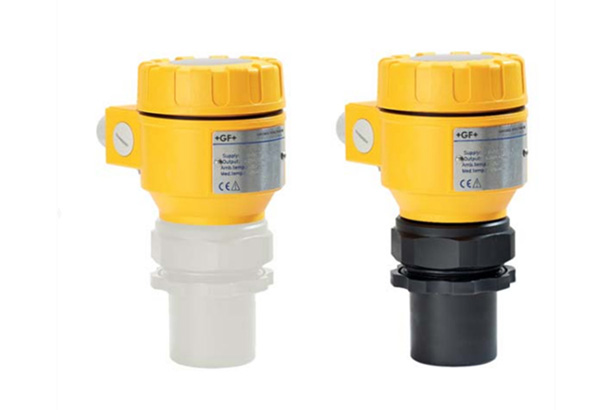
The GF Signet 2260 is an ultrasonic level transmitter with a 15-meter range, built for tank level monitoring in water treatment, chemical storage, and industrial process applications. Connecting it to a PLC is straightforward — it outputs a standard 4-20 mA analog signal — but getting a stable, correctly scaled level reading depends on a handful of wiring and configuration decisions that are easy to miss.
What Output Does the GF Signet 2260 Provide?
The 2260 is a loop-powered 4-20 mA transmitter. It does not need a separate power supply — the same two wires carry both the DC power (12–36 VDC) and the 4-20 mA current signal proportional to measured level. The 4 mA point corresponds to minimum level (empty tank), and 20 mA corresponds to the maximum span you configure, up to 15 meters.
- Signal type
- 2-wire loop-powered 4-20 mA analog
- Supply voltage
- 12–36 VDC (typical: 24 VDC from PLC power rail)
- Span range
- 0.3–15 meters, configurable via the 2260 setup menu
- Resolution
- 1 mm (0.04 inch)
- Accuracy
- ±0.25% of range
- Enclosure rating
- NEMA 4X / IP65
Wiring the 2260 to a PLC Analog Input
The 2260 uses a two-wire loop. The same two terminals handle both power and signal — no separate excitation wiring is needed:
-
Identify the 2260 terminals. Inside the housing, two screw terminals are labeled
+and−(orL+andL−on some revisions). -
Power from the PLC analog input card. Most PLC analog input modules supply loop power internally. The module
I+terminal connects to the 2260+terminal, and the 2260−terminal returns to the moduleI−or COM terminal. -
If the PLC module does not provide loop power, insert an external 24 VDC supply in series. Wire: power supply
+→ 2260+, 2260−→ analog inputI+, analog inputI−→ power supply−. - Use shielded twisted-pair cable (Belden 8760 or equivalent, 18–22 AWG). Ground the shield at the PLC panel end only — grounding at both ends creates a ground loop.
Scaling the Signal in the PLC
Once the 4-20 mA loop is wired, scale the raw analog count to engineering units. The 2260 outputs 4 mA at empty and 20 mA at the full span you configured:
- 4 mA → 0% of span → empty (minimum distance)
- 20 mA → 100% of span → the maximum distance set on the 2260
- For a 10-meter tank: 4 mA = 0 m, 12 mA = 5 m, 20 mA = 10 m
In Allen-Bradley RSLogix, use the SCP (Scale with Parameters) instruction. In Siemens TIA Portal, use SCALE_X and NORM_X. The raw input range on a 16-bit analog input module is typically 0–32767, where 4 mA corresponds to roughly 6554 counts and 20 mA to 32767 counts — verify your specific module data sheet for the exact mapping.
After scaling, apply a small deadband of 0.1–0.3% of span. Ultrasonic transmitters are sensitive to surface ripple, and an unfiltered signal can cause nuisance alarms or erratic pump cycling on the PLC side.
Pairing the 2260 with a GF Signet 9900 Display
If the installation needs a local readout alongside the PLC signal, the GF Signet 9900 single-channel transmitter serves as both a local indicator and a signal pass-through. The 2260 connects to the 9900 via the Signet sensor input, the 9900 displays level locally on a backlit LCD, and the 9900 retransmits the signal through its own 4-20 mA output to the PLC.
The 9900 adds a local display, two relay outputs for high/low level alarms, and a configurable 4-20 mA output — all without changing the wiring scheme to the PLC. It is the simplest path to adding a local readout to a 2260 installation already feeding a control system.
Common Installation Pitfalls
- Ground loops
- Shield grounded at both ends creates a current path for electrical noise. Ground the cable shield at the PLC panel end only.
- Insufficient supply voltage at distance
- The 2260 needs at least 12 VDC at its terminals. A 24 VDC supply at 300 meters of 22 AWG drops about 6 V, leaving 18 V at the transmitter — fine. But at 600 meters on 24 AWG, the drop approaches 12 V and the transmitter will brown out. Size the wire accordingly.
- Mounting too close to the tank wall
- Ultrasonic transmitters need a clear beam path. Mount the 2260 at least 30 cm from the tank wall. The beam angle is roughly 5–7 degrees, meaning the beam diameter at 10 meters is approximately 1 meter — a wall that close will generate false echoes.
- Unfiltered signal causing PLC chatter
- A rippling liquid surface modulates the ultrasonic return strength. Without a deadband or averaging filter in the PLC logic, the level reading oscillates by a few percent — enough to cycle pumps or trigger false alarms.
Can I use the 2260 with a PLC that only accepts 0-10 V input?
Yes, with a 250 Ω precision resistor wired across the analog input terminals. The 4-20 mA current through 250 Ω produces 1–5 VDC: 4 mA × 250 Ω = 1 V, 20 mA × 250 Ω = 5 V. Scale the 0-10 V input to read 0–100% level across the 1–5 V range. Some analog input cards have a built-in current-to-voltage conversion via a dip switch — check the module documentation before adding an external resistor.
What is the maximum cable distance between the 2260 and the PLC?
With 24 VDC supply and 18 AWG shielded twisted-pair, the 4-20 mA loop can reach roughly 900 meters before voltage drop limits the transmitter. At 300 meters of 22 AWG, the loop voltage drop is about 6 V, leaving 18 V at the transmitter from a 24 V supply — well within the 12 V minimum. For distances beyond 500 meters, use 18 AWG or larger and verify the supply voltage at the transmitter terminals with a multimeter before commissioning.
Do I need a separate power supply or does the PLC power the 2260?
Most modern PLC analog input modules provide internal loop power (often labeled "2-wire transmitter excitation" or "loop power"). If your module supports this, no external supply is needed — the two wires between the PLC card and the 2260 handle both power delivery and signal return. If your module is a 4-wire input with separate power and signal terminals, you must add an external 24 VDC supply in the loop. Check the module wiring diagram to confirm.