A baghouse in a cement plant runs 24 hours a day. The filter bags inside accumulate a dust cake that thickens by the hour, raising pressure drop across the collector. Every 30 seconds, a bank of pulse jet solenoid valves fires — each releasing a 50- to 150-millisecond burst of compressed air down a blowpipe and into a row of filter bags. The shock wave snaps the dust cake off the fabric and into the hopper. A 1,000-bag collector might have 100 pulse valves, each firing thousands of times per day. If a valve is undersized, the bags in that row clean incompletely, differential pressure creeps up, and the main fan pulls more amps for less airflow. If a valve is oversized, compressed air consumption erodes the operating budget — and a single oversized valve can waste more energy in a year than it cost to buy. This guide covers pulse jet valve sizing, diaphragm material selection, pilot configuration, tank pressure, blowpipe alignment, and installation — so you can match the valve to the baghouse, not the datasheet.
How a Pulse Jet Valve Cleans a Filter Bag
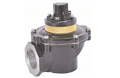
A pulse jet valve is a diaphragm-type solenoid valve that opens against a pressurized air reservoir. When the solenoid coil energizes, it vents the pressure above the diaphragm. The diaphragm lifts, and the full tank pressure — typically 4.5 to 6.9 bar (65 to 100 psi) — discharges through the valve orifice into a blowpipe in under 150 milliseconds. The resulting shock wave travels down the blowpipe and through venturi nozzles into each filter bag, momentarily reversing airflow and flexing the fabric to shed the dust cake.
The key performance parameters are not just pressure and flow. Opening speed matters as much as orifice size — a valve that opens slowly wastes tank pressure during the transition instead of delivering it as a crisp shock wave. Closing speed matters equally: a valve that closes sluggishly bleeds tank pressure between cleaning pulses and delays the next firing. A baghouse cleaning cycle is only as precise as the valve response time allows.
What orifice diameter do I need for my baghouse?
The valve orifice diameter determines how much air volume each pulse delivers, and it must match the number and length of filter bags in a row. A 3/4-inch (19 mm) orifice valve can clean 6 to 10 bags with lengths up to 3 meters. A 1-inch (25 mm) orifice handles 8 to 14 bags up to 4.5 meters. A 1.5-inch (38 mm) orifice covers 12 to 18 bags up to 6 meters. For large baghouses with 8-meter bag lengths, 2-inch (51 mm) and 2.5-inch (64 mm) orifice valves are standard — these deliver the air volume necessary to propagate the shock wave the full bag length without dissipating before reaching the closed end.
Undersizing a valve produces incomplete cleaning at the far end of the bag — the shock wave loses energy before traveling the full length, leaving a residual dust cake that raises baseline pressure drop. Oversizing wastes compressed air and can physically damage bags: an excessively powerful pulse can tear the fabric at the cuff or blow bags off their cages. The cost penalty is asymmetric — compressed air at 7 bar costs roughly 0.02 to 0.03 kWh per cubic meter, so a single oversized valve firing every 30 seconds adds up to several hundred dollars per year in unnecessary energy cost.
Diaphragm Material: Temperature, Chemistry, and Cycle Life
The diaphragm is the wearing component inside every pulse jet valve. It sees full tank pressure on one side, atmospheric on the other, and flexes with every firing cycle. Material selection depends on three variables: operating temperature, chemical exposure in the compressed air supply, and expected cycle count.
- Nitrile (NBR)
- Standard material for clean, dry compressed air up to 82°C (180°F). Good abrasion resistance and low cost. Not suitable for air containing oil mist above 5 ppm or ozone from older compressor systems.
- Viton (FKM)
- For compressed air supplies above 82°C up to 175°C (350°F). Resistant to oil mist and mild chemical carryover. The standard choice for cement kiln baghouses and high-temperature process dust collectors where radiant heat from the tube sheet raises valve body temperature.
- PTFE
- For chemically aggressive environments — pharmaceutical drying, chemical reactor vent collection, acid gas scrubbing. Temperature range -30°C to 200°C (-22°F to 392°F). Stiffer than NBR and FKM, which slightly slows opening speed — compensate with 0.3 to 0.5 bar higher tank pressure.
- Silicone
- For low-temperature applications down to -50°C (-58°F) where NBR stiffens and loses flexibility. Common in cold-climate dust collectors on outdoor installations. Limited oil resistance — do not use if compressor lubricant carryover exceeds 1 ppm.
Integrated Solenoid Pilot vs. Remote Pilot
Pulse jet valves are available with two pilot configurations: an integrated solenoid coil mounted directly on the valve body, or a remote pilot solenoid connected via small-bore tubing. The choice affects maintenance access, electrical installation, and operating cost.
Integrated solenoid valves put the coil on the valve — one electrical connection per valve, simplest wiring, fastest response. But the coil sits in the compressed air environment and is exposed to vibration from every pulse. When a coil fails, you replace it at the valve location, which may require a ladder or platform access in a tall baghouse. Typical coil life is 3 to 5 million cycles under normal conditions.
Remote pilot valves use a central bank of solenoids — often mounted at ground level — connected to each pulse valve via small-diameter pilot tubing. One remote solenoid can serve a single pulse valve or a small group fired simultaneously. The advantage is ease of maintenance — solenoid replacement happens at floor level, not on a ladder. The trade-off is a slightly slower valve opening (8 to 15 milliseconds additional pilot signal propagation time) and the added cost and leak potential of pilot tubing runs. Remote pilot makes sense when the baghouse tube sheet is above 8 meters, or when maintenance access is constrained.
When should I choose remote pilot over integrated solenoid?
Choose remote pilot when maintenance access to the valve location requires scaffolding or a manlift, when the baghouse atmosphere exceeds the solenoid coil's temperature rating, or when you have more than 50 valves and centralizing the electrical terminations at floor level reduces wiring labor more than the pilot tubing adds. Stay with integrated solenoid when the baghouse has walk-in access at the tube sheet level, the environment is below 50°C (122°F), and you want the fastest possible valve response for precise cleaning timing.
Tank Pressure, Blowpipe Design, and Compressed Air Consumption
The compressed air reservoir — the tank or header feeding the pulse valves — must maintain pressure within 0.3 bar (5 psi) of the setpoint throughout the cleaning cycle. If the reservoir is undersized, the last valves in the firing sequence see lower pressure than the first, producing uneven cleaning across the baghouse. A practical rule: the reservoir volume should be at least 1.5 times the total air volume released in one complete cleaning cycle (all valves firing once).
Blowpipe diameter and venturi alignment directly affect cleaning effectiveness. The blowpipe inner diameter should match the valve orifice diameter at the valve end and remain consistent to the last nozzle. Each venturi nozzle must center over its filter bag opening within 3 mm (1/8 inch) — misalignment beyond this causes the pulse jet to strike the bag wall instead of flowing down the center, reducing cleaning energy by 30 to 50% for that bag. Install the blowpipe with its centerline 25 to 75 mm (1 to 3 inches) above the bag openings for optimum entrainment of secondary airflow, which amplifies the cleaning pulse by drawing surrounding clean air into the bag.
How much compressed air does a pulse jet system consume?
A single pulse valve firing at 5.5 bar (80 psi) through a 1-inch orifice for 100 milliseconds consumes approximately 0.06 to 0.09 cubic meters (2 to 3 cubic feet) of free air per pulse. For a 100-valve baghouse firing every 30 seconds, that is roughly 12 to 18 m³/hour (420 to 630 ft³/hour) — about 10 to 15% of the total compressed air demand in a typical cement mill. The exact consumption depends on tank pressure, valve orifice size, and pulse duration. A pulse duration timer set 20 milliseconds too long on every valve wastes 20 to 25% more compressed air than necessary without improving cleaning. Verify that bags are cleaning adequately at the shortest pulse duration that works, then add 10 milliseconds as a safety margin.
Installation: Manifold Mounting, Wiring, and Blowpipe Alignment
Pulse valves mount directly to the compressed air manifold — a common header tank running the length of the baghouse. Install each valve with its diaphragm vertical (coil pointing upward or horizontally outward) to ensure condensate drainage through the exhaust port. Valves mounted upside-down trap moisture above the diaphragm and fail early.
Wiring for integrated solenoid valves typically uses a multi-conductor cable with one pair per valve, home-run to a sequential timer controller. The timer fires valves in a programmed sequence — usually one row at a time, with a 10- to 30-second interval between rows so the dust dislodged from one row settles into the hopper before the next row fires. Wire gauge: 18 AWG is adequate for runs under 30 meters with a 6-watt coil; size up to 16 AWG for longer runs or higher-wattage coils.
Why do pulse jet valves fail early, and how do I prevent it?
The three most common failure modes are moisture damage, dirt ingress, and diaphragm fatigue. Moisture from wet compressed air condenses inside the valve body, corroding the solenoid armature and causing the diaphragm to stick. The fix: a properly sized compressed air dryer and an automatic condensate drain on the reservoir tank. Dirt ingress through worn exhaust port mufflers scores the diaphragm seat and causes slow leaks — replace exhaust mufflers annually in dusty environments. Diaphragm fatigue from over-cycling appears as radial cracks visible on inspection — if a valve cycles more than 1 million times per year, schedule diaphragm replacement at 3-year intervals regardless of apparent condition.
Related Content
- Browse all solenoid valves — full range of direct-operated, pilot-operated, and process solenoid valve solutions
- Pneumatic cylinders — complementary pneumatic actuation components for dust collector damper and discharge systems
- Control valves — modulating and on/off valve solutions for industrial process control