A cold rolling mill reduces steel strip from 2–6 mm entry gauge down to 0.1–1.5 mm exit gauge, with thickness tolerances tightening every decade—automotive exposed panels now demand ±0.5% of nominal gauge, and silicon steel for transformer laminations demands ±3 µm absolute across a 1,200 mm wide strip. The thickness gauge that closes the AGC (automatic gauge control) loop determines whether the mill hits those numbers. Three measurement technologies compete for this role: contact (isotope/shielding gauge with physical reference), laser triangulation, and X-ray transmission. Each interacts differently with strip surface finish, alloy composition, and mill vibration—and the choice has consequences measured in scrap tonnes per shift.
How contact thickness gauges work in cold mills
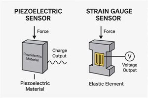
Contact gauges—historically using radioisotope sources (Am-241, Kr-85) but increasingly replaced by X-ray tubes—use a C-frame that physically straddles the strip. The measurement principle is radiation absorption: the intensity of radiation transmitted through the strip is inversely proportional to thickness, following the Beer-Lambert law. A detector on the opposite side of the C-frame measures the attenuated beam; the system computes thickness from the attenuation ratio. Despite the "contact" name, the gauge head does not touch the strip—it rides on an air bearing or mechanical guide that maintains a fixed standoff of 2–5 mm. What makes it "contact" is the C-frame's physical proximity to the strip: the frame must wrap around the strip edge, which limits access near the strip edges and requires the gauge to retract during strip threading. Accuracy is ±0.1% of reading or ±0.5 µm, whichever is larger, for steel strip in the 0.1–6 mm range.
How laser triangulation gauges work
Laser triangulation projects a focused laser spot onto the strip surface and images the reflected spot onto a linear CCD or CMOS sensor at a known angle. As the strip thickness changes, the spot position on the detector shifts; the system computes the displacement from the triangulation geometry. To measure thickness, two laser heads—one above, one below the strip—measure their respective distances to the surface. The thickness is the difference between the known head-to-head separation and the sum of the two measured distances. Laser gauges are truly non-contact, with a standoff of 50–200 mm, and can be positioned anywhere across the strip width without a C-frame to restrict access. Accuracy is ±1–3 µm for a single-point measurement on clean, stable surfaces.
How X-ray transmission gauges work
X-ray gauges replace the radioisotope source with an X-ray tube operating at 10–160 kV. Like the isotope gauge, they measure thickness from the attenuation of the beam passing through the strip. But because the X-ray tube's energy spectrum and intensity are adjustable—unlike a fixed-energy isotope source—the system can optimize the energy for the specific alloy and thickness range, improving signal-to-noise ratio. Modern X-ray gauges achieve ±0.05% of reading accuracy (or ±0.3 µm) on steel strip, with a measurement update rate of 1–10 ms, fast enough to close the AGC loop at rolling speeds exceeding 1,500 m/min. The X-ray source is switched off when the mill stops, eliminating the regulatory burden of continuous radioisotope shielding.
Surface reflectivity and the laser challenge
Cold-rolled steel strip presents a challenging surface for laser triangulation. A freshly rolled surface can have an Ra of 0.2–0.8 µm—nearly mirror-like. On a specular surface, the laser spot reflects directionally rather than diffusely, starving the detector of scattered light and producing erratic readings. Oil and emulsion residue from the rolling process further distort the laser spot shape, introducing systematic errors of 2–5 µm. Laser gauge manufacturers address this through blue/violet laser diodes (shorter wavelength increases diffuse reflection from metal surfaces) and through multi-point averaging that reduces speckle noise. But laser triangulation remains less accurate than radiation-based gauges on bright metal strip—the accuracy gap is roughly 3–5× wider on low-Ra surfaces. Contact/X-ray gauges are immune to surface reflectivity because they measure bulk material attenuation, not surface-scattered light.
Alloy compensation: why X-ray wins on mixed grades
Radiation absorption in steel depends on both thickness and alloy composition. A 0.8 mm strip of stainless steel (high chromium and nickel content) attenuates differently than 0.8 mm of low-carbon steel. Contact gauges using isotope sources have fixed-energy beams and must be calibrated for each alloy group—typically with a lookup table of alloy compensation factors. Running a mixed-grade coil schedule means the gauge operator must select the correct alloy setting at each coil change; a wrong selection produces a systematic thickness error of 2–8%. X-ray gauges address this through multi-energy measurement: by switching between two or three tube voltages in rapid succession, the system measures attenuation at multiple energies and solves for both thickness and effective atomic number simultaneously. This "alloy-independent" measurement eliminates the operator-selectable alloy table and its associated error risk. For mills running 20+ different steel grades per shift, this feature alone typically justifies the X-ray premium.
Vibration, pass-line variation, and measurement robustness
Cold mills vibrate. The work rolls chatter at 100–300 Hz during high-speed rolling; the mill housing shakes; the strip flutters vertically as it exits the roll bite. A laser triangulation gauge measuring the strip 500 mm downstream of the roll bite sees pass-line position changes of ±0.5–1.0 mm due to strip shape and vibration. Since the thickness calculation subtracts two large distance measurements (typically 80–120 mm each) to yield a small thickness value (0.5–2.0 mm), a 0.5 mm pass-line shift—if uncorrected—produces roughly a 0.5 mm thickness error, or 50% of a 1 mm strip. This is the core vulnerability of laser triangulation in mill environments. C-frame gauges (contact and X-ray) fix the upper and lower detector positions relative to each other via the rigid C-frame structure, making them inherently insensitive to pass-line variation. The C-frame itself is mechanically isolated from mill vibration through a dedicated mounting structure bolted to the mill foundation, not the mill housing.
Where each technology fits in a cold mill
| Technology | Best Application | Key Limitation |
|---|---|---|
| Contact/Isotope Gauge | Single-alloy mills, retrofit of existing C-frame installation | Regulatory burden of isotope source; alloy-dependent calibration |
| Laser Triangulation | Roughing stands, edge-drop measurement, non-metallic strip | Surface-reflectivity errors; pass-line sensitivity |
| X-Ray Transmission | Finishing stands, mixed-grade mills, AGC feedback for ±0.5% tolerance | Higher capital cost (€80k–€150k installed) |
The sensor and instrumentation landscape for cold mill gauging continues to shift as X-ray source miniaturization and high-speed signal processing close the cost gap with legacy isotope systems. For mills targeting sub-±1% gauge tolerance on a mixed-grade schedule, the X-ray gauge has become the default choice in new installations.
The Thermo Fisher Scientific RM 210 X-ray thickness gauge delivers ±0.05% accuracy with multi-energy alloy compensation and a 1 ms measurement update rate—designed to close the AGC loop on tandem cold mills rolling automotive exposed and silicon steel grades.