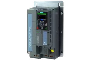
You are standing in front of a newly installed SINAMICS G120. The motor cables are terminated, the 400 V supply is landed, and the control wiring is complete. But the commissioning engineer with the laptop and the Starter software is booked for another three days. The line needs to run tomorrow. The IOP-2 — a palm-sized handheld operator panel that plugs directly into the G120 Control Unit — was designed for exactly this situation.
The IOP-2 (Intelligent Operator Panel 2) is a removable color LCD keypad that performs basic and advanced commissioning, parameter backup and restore, drive cloning, and diagnostics — all without a laptop, without software installation, and without a PROFINET connection to the drive. This guide walks through the commissioning workflow, from first power-up to a motor spinning under load, using only the IOP-2.
What the IOP-2 Is — and What It Is Not
The IOP-2 is a 3-inch color graphical display with a 4-way navigation pad, a numeric keypad, and context-sensitive function keys. It plugs into the CU (Control Unit) faceplate of any SINAMICS G120, G120X, or G120P drive via a 20-pin connector — no cable, no mounting bracket, just press it into the socket and turn the locking screw. The G120X Starter Kit ships with the IOP-2 included, and it is compatible with the CU240E-2 Control Unit across the entire G120 family.
It is not a replacement for a full engineering tool. The IOP-2 cannot configure free function blocks, cannot create Drive Control Chart (DCC) diagrams, and cannot set up safety functions (STO/SS1/PROFIsafe — those require a laptop with Starter or Startdrive). But for the 80% of commissioning tasks that involve entering motor nameplate data, setting ramp times, configuring I/O, and testing the motor, the IOP-2 handles the entire workflow on its own.
The IOP-2 also serves as a maintenance tool. A technician doing a preventive maintenance round can plug it into any G120 on the floor, read the active alarm log, check the DC-link voltage trend, and save the parameter set to the IOP-2's internal memory — 100 parameter sets on a single device. This is faster than connecting a laptop, launching software, and going online, especially on a noisy factory floor where balancing a laptop on a control cabinet door is a two-hand job.
Step 1: Apply Power and Start the Basic Commissioning Wizard
Apply 24 V DC control power to the CU first — the IOP-2 boots from the CU's internal power supply. Wait approximately 10 seconds for the IOP-2 to initialize and display the home screen. The home screen shows the drive status (Ready, Run, Fault), the current speed or frequency setpoint, and four soft-key labels across the bottom of the screen.
Press the right-hand soft key labeled Menu. Navigate using the arrow keys to Wizards → Basic Commissioning. The wizard is a linear sequence of roughly 15 screens — it asks one question per screen, and your answer determines which screen comes next. There are no branches, no conditional logic to manage, and no parameter numbers to memorize. Each screen presents the current setting or a default and lets you accept or change it.
The key screens in sequence: select motor standard (IEC or NEMA) → enter motor rated voltage (from nameplate) → motor rated current → motor rated power → motor rated frequency (50 or 60 Hz) → motor rated speed (RPM) → motor cooling method (self-cooled or forced ventilation) → application type (pump/fan, conveyor, or general) → ramp-up time → ramp-down time → minimum frequency → maximum frequency → command source (IOP-2 keypad, terminal, or fieldbus) → setpoint source.
For a standard 4-pole IEC motor at 400 V / 50 Hz, the motor data entry takes roughly two minutes — the nameplate values are printed on the motor, and each screen asks for exactly one value. The wizard does not require you to know parameter numbers; it hides the parameter mapping behind the plain-language screens.
Step 2: Motor Identification (Static and Rotating)
After the wizard completes, the IOP-2 prompts you to run motor identification. This is a one-time measurement where the drive injects test signals into the motor windings to measure stator resistance, leakage inductance, and magnetizing inductance — the values the drive's vector control algorithm needs to calculate the optimal flux and torque.
You have two options on the IOP-2: Static measurement (motor does not rotate, takes about 1 minute) or Rotating measurement (motor spins at low speed, takes about 2 minutes, more accurate). Choose static measurement if the motor is coupled to a load that cannot be disconnected — the conveyor belt stays still, and the drive measures only the electrical parameters. Choose rotating measurement if the motor can spin freely — uncoupled, or the belt can run empty — and you want the most accurate torque control.
Navigate to Menu → Commissioning → Motor identification, select the measurement type, and press Start. The IOP-2 displays a progress bar and the current measurement step. When complete, it shows "Motor ID successful" and displays the measured values. Press Accept to write them into the drive parameters.
Step 3: Set the Command and Setpoint Sources
For the initial test run, keep the command source on the IOP-2 keypad — this lets you start and stop the motor directly from the handheld panel. Press the green Start key on the IOP-2. The drive ramps the motor to the minimum frequency (typically 5 Hz) and displays the actual speed, output current, and DC-link voltage on the IOP-2 screen. Press the up arrow to increase the speed; the motor accelerates smoothly according to the ramp-up time set in the wizard.
Monitor three values during the test run: output current (should be below motor rated current at no load), DC-link voltage (should be roughly 1.35 × AC input voltage — approximately 540 V DC for a 400 V AC supply — and stable), and motor temperature if a PTC or KTY sensor is wired to the CU terminals. If the current is within range, the DC-link is stable, and the temperature is normal, the drive and motor are correctly commissioned.
Once the test run is successful, change the command source to the actual control method: terminal strip for hardwired start/stop from a PLC digital output, or fieldbus for PROFINET/PROFIBUS control. Navigate to Menu → Parameters → Command source and select the appropriate source. The IOP-2 can remain plugged in as a display during normal operation, or it can be removed — the drive retains all settings in the CU non-volatile memory.
Step 4: Save and Clone the Parameter Set
After commissioning is complete, save the parameter set to the IOP-2 internal memory: Menu → Extras → Save to panel. Name the file with the conveyor zone identifier — for example, "Zone12_Infeed_2.2kW" — and the IOP-2 stores the complete parameter set plus the motor identification results.
If the next drive on the line is identical — same motor, same application, same I/O configuration — you do not need to run the wizard again. Plug the IOP-2 into the next CU, navigate to Menu → Extras → Load from panel, select the saved file, and the IOP-2 writes all parameters to the new drive in under 30 seconds. Run motor identification for the specific motor (each motor's stator resistance is slightly different), and the drive is commissioned. For a 30-drive conveyor line with 10 identical zone types, you run the wizard once, clone it nine times, and run motor ID on each — total commissioning time under two hours.
When You Still Need a Laptop
The IOP-2 has limits. It cannot configure PROFIsafe safety functions — those require Starter or Startdrive with a safety-qualified connection. It cannot set up free function blocks for custom interlocks or sequencing logic. It cannot perform trace recordings for hunting or instability troubleshooting — you need a laptop with the trace function in Starter to capture high-speed data on the drive internal signals.
And the IOP-2 cannot commission a drive that has never been powered before if the CU firmware is incompatible — a firmware update requires a laptop with the Siemens firmware update tool. If the IOP-2 displays "Firmware incompatibility" when you plug it in, you need a laptop — but once the firmware is updated, the IOP-2 handles everything else.
How long does a full IOP-2 commissioning take on a typical conveyor drive?
For a standard 4-pole motor on a belt conveyor, budget 10 minutes from power-up to motor running under keypad control: 2 minutes for the wizard, 2 minutes for motor identification, 2 minutes for a no-load test run, and 4 minutes for I/O configuration and command source setup. If you are cloning a saved parameter set to an identical drive, the time drops to 3 minutes: 30 seconds to load the parameter file, 2 minutes for motor identification on the new motor, and 30 seconds to verify the test run.
Can I use the IOP-2 on a drive that is already running a process?
Yes — with caution. Plugging in the IOP-2 does not interrupt drive operation. The drive continues running on its existing command source and setpoint. The IOP-2 displays the current operating values and alarm log. However, do NOT run the basic commissioning wizard on a running drive — the wizard assumes the drive is stopped and will fault if the drive is in Run state. For a running drive, use the IOP-2 for monitoring, diagnostics, and parameter backup only.
The IOP-2 turns drive commissioning from a scheduled engineering visit into a technician task. The wizard asks one question at a time. The cloning function turns 30 identical drives into one commissioning and 29 copy operations. And when the laptop engineer finally arrives three days later to set up PROFIsafe, the drives are already running.