
1 / 5
Product Specifications
- Manufacturer
- Littelfuse, Inc.
- Series
- MPS (Motor Protection System)
- Product Type
- Digital Motor Protection Control System
- Protective Functions
- 22 protective functions (overload, unbalance, phase loss/reverse, overcurrent/jam, undercurrent, ground fault, RTD temp, overvoltage, undervoltage, voltage unbalance, phase differential, etc.)
- Core Hardware (CTU)
- 5 relay outputs (3 Form A + 2 Form C), 8 digital inputs, 1 × 4‑20 mA analog input & output; 24 V DC supply for accessories
- Optional Modules
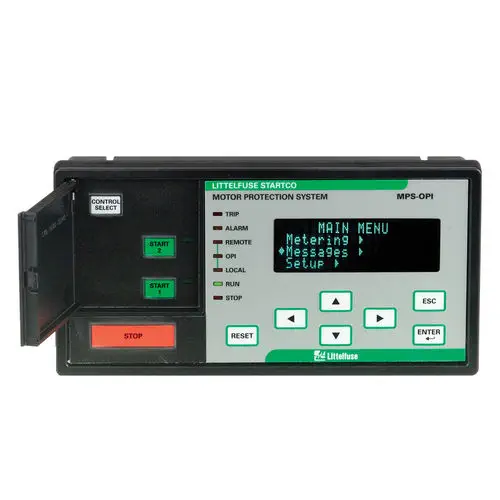
- MPS-OPI (4 × 20 VFD operator interface, 1/2 DIN, hazardous-location certified); MPS-RTD (8 programmable RTD inputs, up to 24 sensors); MPS-DIF (3-CT core balance/6-CT summation differential protection)
- Communications
- RS‑485 (Modbus) standard; DeviceNet™, Profibus®, Ethernet optional; IRIG‑B time‑code input
- Power & Certifications
- 65‑265 V AC, 25 VA / 80‑275 V DC, 25 W; startup 800 ms; ride‑through ≥100 ms; CSA, RCM, UL certified
Product Description
The Littelfuse MPS (Motor Protection System) is a comprehensive, modular motor protection relay designed to monitor and protect three-phase induction motors in demanding industrial environments. It provides 22 configurable protective functions, encompassing overload, voltage, current, temperature, and phase monitoring. The system is built around a central control unit (MPS-CTU), which can be expanded with an operator interface, RTD temperature module, and differential protection module, offering a tailored solution for critical assets in mining, oil & gas, power generation, and heavy manufacturing.
Central Control Unit (MPS-CTU) — The Core of the Protection System
- Comprehensive Electrical Protection: The MPS-CTU continuously monitors voltage (up to 600 V direct, without PTs), phase current (5 A/1 A CT secondary), and equipment temperature. It provides a portfolio of 22 protective functions, including overload (49), phase unbalance/loss/reversal (46/47), locked-rotor/jam (51), overcurrent (50), undercurrent (37), ground fault (50G/N), over/under voltage (59/27), and voltage unbalance.
- Built-in I/O and Power Supply: The CTU features eight programmable digital inputs, five relay outputs (three Form A, two Form C), one 4-20 mA analog input, and one 4-20 mA analog output. A built-in 24 V DC supply powers the optional OPI and RTD modules directly from the CTU, eliminating the need for an external power source for these accessories. The unit operates on a wide-range power supply: 65–265 V AC (25 VA) or 80–275 V DC (25 W), with an 800 ms startup time and a 100 ms minimum ride-through time to maintain protection during brief voltage dips.
- Modbus RTU Communication (Standard): The standard RS‑485 port supports Modbus RTU protocol, and IS2000 or via Littelfuse software. An IRIG‑B input port for satellite time synchronization allows events across multiple units to be correlated to within one millisecond for precise root cause analysis.
Flexible Expansion Through Optional Modules
- Operator Interface (MPS-OPI): The OPI is a large, bright 4 × 20 vacuum-fluorescent display that provides local access to all measured values and setpoints without requiring a PC. It is 1/2 DIN size, can be mounted directly on the CTU or panel-mounted, and can be installed up to 1.2 km (4,000 ft) away from the CTU via shielded twisted-pair cable. It is rated for use in hazardous locations.
- RTD Temperature Module (MPS-RTD): This optional module adds eight programmable RTD inputs, supporting Pt100, Ni100, Ni120, and Cu10 sensors. Up to three modules can be combined to monitor 24 RTD points, enabling bearing, stator, and ambient temperature protection (38/49). The module includes an internal 24 V DC power supply and can be mounted up to 1.2 km from the CTU.
- Differential Module (MPS-DIF): For the highest level of winding fault protection, the differential module monitors the current entering and leaving the motor, detecting phase-to-phase faults and turn-to-turn shorts that are invisible to phase overcurrent protection. It supports both 3-CT core balance (harmonic suppression) and 6-CT summation current transformer connections, with a configurable current threshold of 100–300% of motor full-load current.
System Integration, Data Logging, and Remote Communications
- Network Connectivity: Beyond standard RS‑485, the MPS can be ordered with integrated DeviceNet™, Profibus®, or Ethernet communication modules (e.g., MPS-CTU-02-00, MPS-CTU-03-00, MPS-CTU-04-00), enabling direct connection to DCS, PLC, and SCADA systems from various vendors.
- Data Logging and Event Recording: The system logs operational data, alarm events, and waveform captures, providing a complete history for predictive maintenance. This data can be accessed locally via the OPI or remotely through the communication network.
- Certified to Global Standards: The MPS is certified by CSA, RCM (for Australian market), and UL for North American applications, with options for IEC devices such as IEC 60255-1 compliant extended models.
Applications
- Mining: Protection of crushers, conveyor drives, and ball mills where unplanned downtime results in significant production loss
- Oil & Gas: Protection of pumps, compressors, and pipeline drives, with optional differential module for sensitive winding fault detection in critical applications
- Power Generation: Safeguarding large boiler feed pumps, cooling water pumps, and induced draft fans in coal, natural gas, and nuclear power stations; IRIG‑B time sync for accurate event sequencing
- Heavy Manufacturing: Protection of extruders, mixers, and rolling mills in steel, cement, and paper industries
- Water and Wastewater: Comprehensive protection including voltage monitoring and RTD temperature for large, critical pump motors in treatment plants and distribution networks
Resources & Documentation
Littelfuse
Compare
Motor Protection System, 22 Protective Functions, Modular RTD/DIF – MPS | Littelfuse
IRIG-B Time Sync, Data Logging
MPN/Series: MPS Series
Product Specifications
- Manufacturer
- Littelfuse, Inc.
- Series
- MPS (Motor Protection System)
- Product Type
- Digital Motor Protection Control System
- Protective Functions
- 22 protective functions (overload, unbalance, phase loss/reverse, overcurrent/jam, undercurrent, ground fault, RTD temp, overvoltage, undervoltage, voltage unbalance, phase differential, etc.)
- Core Hardware (CTU)
- 5 relay outputs (3 Form A + 2 Form C), 8 digital inputs, 1 × 4‑20 mA analog input & output; 24 V DC supply for accessories
- Optional Modules
- MPS-OPI (4 × 20 VFD operator interface, 1/2 DIN, hazardous-location certified); MPS-RTD (8 programmable RTD inputs, up to 24 sensors); MPS-DIF (3-CT core balance/6-CT summation differential protection)
- Communications
- RS‑485 (Modbus) standard; DeviceNet™, Profibus®, Ethernet optional; IRIG‑B time‑code input
- Power & Certifications
- 65‑265 V AC, 25 VA / 80‑275 V DC, 25 W; startup 800 ms; ride‑through ≥100 ms; CSA, RCM, UL certified