A humidity transmitter that silently drifts 2% RH over six months is worse than one that fails outright — the failed unit gets replaced, but the drifting one keeps generating bad data that passes every spot check. The Rotronic HygroFlex5A includes trend logging and alarm tracking specifically to catch this failure mode. This article covers how to set up data logging, interpret the trend output, and use that data to schedule maintenance on your terms rather than the batch failure's terms.
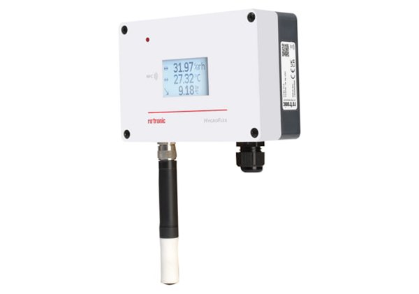
The HygroFlex5A is an industrial humidity and temperature transmitter built around Rotronic's AirChip4000 digital signal processing platform. It accepts any HygroClip2 digital probe — which stores its own calibration data on-board — and outputs relative humidity, temperature, dew point, and calculated parameters over two analog outputs and a digital Modbus RTU interface. The "A" variant is configured for HVAC and industrial measurement applications, operating on 24 VAC/VDC with a wall-mount enclosure rated IP65.
HygroFlex5A vs. HygroFlex5 vs. HygroFlex3: Which Model Has the Logging You Need?
Rotronic's HygroFlex transmitter family spans three generations with different data handling capabilities:
- HygroFlex5A — AirChip4000 platform with HygroClip2 digital probe compatibility, on-board trend logging with configurable intervals, two analog outputs plus Modbus RTU, designed for HVAC and light industrial measurement
- HygroFlex5 — same AirChip4000 platform and HygroClip2 compatibility, available as a kit with probe included, supports wall-mount installation for building automation
- HygroFlex3 — earlier-generation transmitter with analog HygroClip probe interface, basic 4–20 mA output only, no digital logging or Modbus — suitable for simple HVAC control loops where trend data is not required
The key distinction: if you need trend analysis, you need the AirChip4000 platform in the 5A or 5. The HygroFlex3 is a reliable analog transmitter, but it cannot store or trend data — it reports the current value and nothing more.
Setting Up Trend Logging on the HygroFlex5A
The HygroFlex5A stores logged data points at a user-configurable interval — typically 1 to 60 minutes — with each data point recording RH, temperature, dew point, and any active alarm flags. Logging is configured through the Rotronic HW4 software (via the USB service interface) or through Modbus register writes if you are integrating into a building management system.
To start trend logging:
- Connect the HygroFlex5A to a PC using the Rotronic service cable (USB-to-UART adapter) and launch HW4 software.
- In the device configuration panel, navigate to Data Logging and set the logging interval. For HVAC stability validation, a 5-minute interval captures meaningful trends; for pharmaceutical storage areas, 1-minute intervals are standard.
- Select Start Logging. The transmitter begins recording to internal flash memory. Logged data persists through power cycles.
- To retrieve data, use HW4's Download Log function, which exports a time-stamped CSV file with RH, temperature, dew point, and alarm status columns.
The internal memory holds approximately 10,000 data points per parameter. At a 5-minute interval, that is roughly 34 days of continuous logging before the oldest data is overwritten in a rolling buffer.
What does a healthy trend look like, and what signals a problem?
A stable HVAC-controlled environment should show RH varying no more than ±2% around the setpoint over a 24-hour log, with temperature variation under ±1°C. The first sign of trouble is usually not a spike but a baseline shift — the entire trace moves up or down by 2–3% RH over several days without correlation to temperature changes. This pattern indicates probe drift, not an environmental issue. The second red flag is an increasing amplitude in the RH cycle — if the daily swing grows from ±2% to ±5%, the HVAC system's humidity control (desiccant wheel, steam humidifier, or cooling coil) is losing authority, and the transmitter is documenting it in real time.
Can I use the HygroFlex5A with probes other than the one it shipped with?
Yes — and this is one of the key advantages of the HygroClip2 digital probe system. Every HygroClip2 probe stores its calibration coefficients in onboard EEPROM. When you plug a different HygroClip2 probe into the HygroFlex5A, the transmitter reads the new probe's calibration data automatically. No manual re-entry of calibration constants is required. This means you can swap between a standard HC2A-S probe for room monitoring and an HC2-LDP low dew point probe for dry air applications without reconfiguring the transmitter. The probe swap takes under 30 seconds and the transmitter resumes logging with the new probe's calibration active.
How often does the HygroFlex5A need calibration, and what do I need?
Rotronic recommends annual calibration for the HygroClip2 probe used with the HygroFlex5A, with a 6-month interval for pharmaceutical GxP applications. The calibration procedure uses a humidity generator — such as the Rotronic HygroGen2 for portable field calibration or the Rotronic HygroCal100A benchtop calibrator for lab-based multi-point verification. A two-point calibration at 35% RH and 80% RH is the standard recommendation for HVAC-range probes. After calibration, the new coefficients are written to the HygroClip2 probe's EEPROM, so the calibration stays with the probe regardless of which HygroFlex5A transmitter it is connected to later.
Integrating the HygroFlex5A into a Broader Monitoring System
For facilities that need centralized monitoring across multiple transmitters, the HygroFlex5A can report trend data to the Rotronic RMS monitoring system — a 21 CFR Part 11 compliant platform that aggregates data from multiple Rotronic devices, provides audit trails, and generates automated deviation reports. A single RMS server can ingest data from dozens of HygroFlex5A transmitters distributed across a pharmaceutical facility or food processing plant.
For simpler setups, the HygroFlex5A's two analog outputs can be wired directly to a building automation system. Configure output 1 for relative humidity (default 0–100% RH = 4–20 mA) and output 2 for temperature or calculated dew point. The Modbus RTU interface provides digital access to all measured and calculated parameters for SCADA integration.