You wire the twisted pair to the transmitter terminals, set the PLC to 9600-8-N-1, and poll register 40001. Nothing comes back — or worse, the flow value reads 65535 and stays there. A magnetic flow meter is inherently a Modbus-capable instrument: the Rosemount 8750W and its companion transmitters speak Modbus RTU over RS-485. But getting the physical layer, register offset addressing, and byte-order configuration right takes more than matching baud rates, and the symptoms of each misconfiguration look surprisingly similar from the SCADA side. This article covers the Modbus setup on Rosemount magnetic flow meters, with specifics that apply to the 8750W, 8712, 8732E, and the broader 8700 series platform.
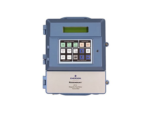
The Rosemount 8750W is a electromagnetic flow meter designed for water and wastewater applications — 1/2 to 48 inch line sizes, PTFE or polyurethane liner, and a 0.25% accuracy specification. It pairs with the Rosemount 8712 or 8732E flow transmitter, which is where the Modbus interface physically lives. The magnetic flow tube (8705 flanged, 8711 wafer, or 8750W integrated) generates a millivolt-level flow signal proportional to the conductive fluid's velocity through the Faraday effect. The transmitter excites the field coils, measures the electrode voltage, converts it to a flow rate, and makes that value available both as a 4-20 mA analog output and as a set of Modbus registers. The Modbus path is the one that gives you totalizer values, diagnostic flags, and multi-variable data that a single 4-20 mA loop cannot carry.
RS-485 Wiring: Two Wires, Multiple Ways to Get It Wrong
The physical layer causes more Modbus failures than any software setting. The Rosemount transmitter's RS-485 terminal block has three positions: A (+), B (−), and a shield/ground terminal:
- Polarity: RS-485 uses differential signaling, and the A/B labeling is not consistent across manufacturers. On Rosemount transmitters, A is non-inverting (+) and B is inverting (−). If the PLC or RTU uses the opposite convention (A = −, B = +), swap the two wires — the bus will not be damaged. The symptom of reversed polarity is no response to any Modbus poll, with the TX LED on the transmitter blinking but no RX activity.
- Biasing and termination: For multi-drop buses with more than two devices or cable runs exceeding 100 meters, install a 120-ohm terminating resistor across A and B at both ends of the bus. The Rosemount transmitter includes a software-selectable internal termination — enable it via Modbus register 0x012C if the transmitter is at the physical end of the daisy-chain. Bias resistors (pull-up on A, pull-down on B) are internal and always active on the 8732E; on the 8712, they are enabled via a hardware jumper.
- Cable type: Use shielded twisted-pair cable with a characteristic impedance of 120 ohms — Belden 3105A or equivalent. The shield must be grounded at one end only (the PLC/RTU end) to prevent ground-loop currents. A shield grounded at both ends couples 50/60 Hz noise onto the data pair through the ground-potential difference between the transmitter enclosure and the control panel.
- Stub length: Each drop from the main bus to a device must be shorter than 1 meter. Longer stubs create impedance discontinuities that reflect the signal and corrupt data at higher baud rates (38.4 kbps and above). For the Rosemount 8750W in a typical plant layout, run the main trunk past each meter location and keep the local drop as short as physically possible.
Modbus Register Map: Finding Flow Rate, Totalizer, and Diagnostics
Rosemount magnetic flow transmitters use a Modbus register map organized around 16-bit holding registers. The register addressing uses the Modicon convention — register 40001 in the PLC corresponds to Modbus address 0x0000 on the wire, and the transmitter expects the PLC to subtract the 40001 offset. The most frequently accessed registers:
- Flow rate (register 40001–40002)
- 32-bit IEEE 754 floating-point value spanning two consecutive 16-bit registers. The byte order (big-endian or little-endian) is configurable via register 0x012A. Default is big-endian (most significant word at the lower register address). If the PLC reads 0x0000 and 0x0000 for a known non-zero flow, check the float byte order setting first — it is the single most common Modbus data error on these transmitters.
- Forward totalizer (register 40003–40004)
- 32-bit unsigned integer, rolls over at 4,294,967,295. For billing or custody-transfer applications, poll this register at least once per PLC scan cycle — the totalizer increments independently of the Modbus poll rate, and missed counts are lost.
- Reverse totalizer (register 40005–40006)
- 32-bit unsigned integer for reverse-flow accumulation. If your application is bi-directional (e.g., a pump station that can back-feed), the net flow is Forward minus Reverse. The transmitter's internal flow-direction logic can be configured to suppress reverse totalization below a configurable low-flow cutoff.
- Diagnostic register (register 40007)
- Bit-mapped status word. Bit 0 = coil drive fault (open or shorted field coils), Bit 1 = empty pipe detection (electrode resistance above threshold), Bit 2 = ADC saturation, Bit 3 = electronics temperature alarm. Monitor this register in the PLC — a non-zero value should latch an alarm in the SCADA system, not just appear on a maintenance screen.
- Conductivity (register 40009–40010)
- 32-bit float, µS/cm. The magnetic flow meter requires a minimum fluid conductivity (typically 5 µS/cm for Rosemount) to measure flow. This register lets you trend conductivity as a proxy for water quality without adding a separate conductivity meter.
What baud rate and parity should I use for the Rosemount 8750W?
The Rosemount 8712 and 8732E support 1200 to 115,200 bps. The default is 9600-8-N-1 (8 data bits, no parity, 1 stop bit). For most water/wastewater SCADA systems, 9600 bps with no parity is adequate — the poll-response cycle for flow rate plus totalizer plus diagnostics takes roughly 50 ms at 9600 bps, which is fast enough for a 1-second PLC scan. If you are polling multiple transmitters on the same RS-485 bus, increase to 19,200 bps to keep the total bus cycle under 500 ms. Avoid 115,200 bps on cable runs longer than 30 meters — at that data rate, cable capacitance rounds the signal edges enough to cause intermittent framing errors, and the resulting retries consume more bus time than a lower baud rate with no retries. Set the parity to even if your Modbus master requires it, but no parity works reliably on properly terminated buses under 500 meters.
What is the difference between the 40001 and 30001 register ranges?
Modbus defines two address spaces: 3xxxx for input registers (read-only) and 4xxxx for holding registers (read/write). On Rosemount magnetic flow transmitters, flow rate, totalizers, and diagnostic status are available in both ranges — you can read flow rate at 30001 (input register, read-only) or 40001 (holding register, read/write). Use the 3xxxx range when all you need is reading — it makes the PLC's intent explicit and prevents accidental writes. The 4xxxx range is required when you also need to write configuration parameters (zero trim, calibration constants, Modbus settings) from the PLC. If your PLC supports function code 04 (Read Input Registers) alongside function code 03 (Read Holding Registers), map the read-only data to 3xxxx and the configuration writes to 4xxxx for cleaner separation. For flow computers and flow computers that do their own totalization from the analog input, the digital totalizer in the Modbus registers serves as an independent audit total — compare the two monthly to detect calibration drift or analog loop errors.
Can I mix Rosemount and non-Rosemount flow meters on the same RS-485 bus?
Yes — Modbus RTU is a multi-vendor protocol by design. Each device on the bus must have a unique Modbus address (1–247), and the register maps do not need to be identical between devices. However, three practical constraints apply on a mixed-vendor bus. First, all devices must use the same baud rate and parity — pick the lowest common baud rate supported by every device. Second, some third-party Modbus masters hard-code register offsets that don't match the Rosemount addressing scheme; test a single register read on the bench before commissioning. Third, the RS-485 electrical standard permits 32 unit loads per bus without a repeater. A Rosemount 8712 or 8732E presents 1/8 unit load, so you can put up to 256 Rosemount transmitters on a single bus before needing a repeater — but a third-party device with a full unit-load transceiver reduces that capacity to 32 per bus. For mixed buses, count unit loads, not just devices. A comparable flow meter from E+H (Proline Promag W 500) or KROHNE (OPTIFLUX 4000) uses the same Modbus RTU protocol, so mixing brands is straightforward — but each brand's register map is different, so the PLC code must be written per-device-type, not per-bus. For Modbus-capable insertion-type meters in large-diameter pipes (36 inches and above), the ICON Truflo MF1000 provides an alternative to full-bore magnetic flow tubes with the same Modbus interface.