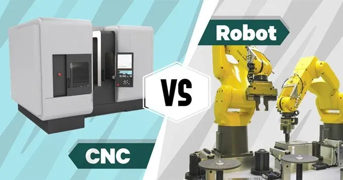
A 6-axis industrial robot with a 15 kW milling spindle mounted at the wrist can trace the same toolpath as a 5-axis CNC machining center. The robot costs $150,000. The CNC costs $800,000. If the part is aluminum, 2 meters long, and toleranced at ±0.25 mm, the robot may produce scrap on the first part and every part after — not because the spindle or the tool is wrong, but because the robot's structural stiffness is 50 to 100 times lower than the CNC's. Understanding where that stiffness deficit matters and where it does not is the difference between a successful robotic machining cell and a very expensive experiment.
Where CNC Stiffness Comes From
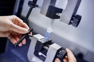
A 5-axis CNC machining center achieves static stiffness of 50–100 N/µm at the tool tip. This comes from a cast iron or mineral-composite machine bed weighing 8–25 tons, box-way or roller-guide linear bearings with preload, and ballscrews with direct-drive or geared servo coupling. When a 5-axis CNC plunges a 20 mm carbide end mill into 6061 aluminum at 5 mm radial engagement, the tool tip deflects less than 2 µm — the cutting force (roughly 200–400 N) divided by the machine stiffness. The part comes out within ±0.01 mm of programmed geometry.
A robot's static stiffness at the tool tip is 0.5–1.5 N/µm — two orders of magnitude below a machining center. The same 400 N cutting force deflects the robot's tool tip by 0.27–0.80 mm. This is not a tuning problem; it is a structural reality of serial-link kinematics.
Robot Stiffness: The Serial-Link Problem
A 6-axis robot is a chain of six rotary joints connected by aluminum or steel links. Each joint has a gearbox — typically a strain-wave gear or RV reducer — with finite torsional stiffness. Stiffness is lowest at the wrist (joints 4–5–6), where small-diameter gears drive the end effector. When cutting force pushes against the tool tip, every joint in the chain deflects slightly, and the deflections accumulate. Joint 2 (shoulder) and joint 3 (elbow) contribute the largest displacement because they have the longest moment arms to the tool tip. The result: the robot's Cartesian stiffness is anisotropic — it varies with arm posture by a factor of 3 to 5. A fully extended arm is 3–5 times more compliant than an arm with the elbow tucked close to the base.
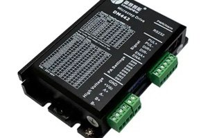
The Y-3023-2-H00AA servo motor class represents the joint-drive technology inside 6-axis robots — high torque density, low inertia, but fundamentally limited by gearbox torsional stiffness. In contrast, CNC ball-screw servos like the Siemens S-1FL6 LI series operate with direct mechanical advantage through leadscrews, giving them a stiffness multiplier of 10–50× over a rotary joint at the same motor torque.
Materials Where a Robot Can Machine
| Material | Cutting Force (N) | Robot Deflection (mm) | Feasible? |
|---|---|---|---|
| Rigid foam / tooling board | 5–30 | 0.01–0.06 | Yes — low force, high margins |
| Carbon fiber composite (trimming) | 30–100 | 0.06–0.20 | Yes — within ±0.5 mm tolerance |
| Aluminum (light finishing) | 100–250 | 0.20–0.50 | Marginal — requires stiff posture, small engagement |
| Aluminum (roughing) | 250–600 | 0.50–1.20 | No — deflection exceeds typical part tolerance |
| Steel / stainless | 400–1200 | 0.80–2.40 | Not feasible without auxiliary stiffening |
Accuracy Compensation: Closing the Gap in Software
Robot machining does not accept the stiffness deficit as a fixed limit. Two compensation strategies reduce effective deflection:
- Posture optimization
- The robot path planner selects arm configurations that maximize stiffness in the direction of cutting force. For a horizontal cutting pass, keeping the elbow close to the body and the wrist aligned with the force vector can triple effective stiffness compared to an extended-arm posture. This is a free improvement — no hardware required — but limits the usable work envelope to the robot's stiffest postures.
- Real-time deflection compensation
- A force-torque sensor at the wrist measures actual cutting forces. The robot controller computes the predicted deflection from a stiffness model of the arm and adds a compensating offset to the toolpath in real time. Commercial systems reduce effective deflection by 50–70%, bringing aluminum finishing into feasibility for many large-part applications. This requires a CNC-grade motion controller like the AXBB-E 6-axis Ethernet CNC controller that runs the stiffness model at the servo loop rate, typically 1–4 kHz.
When a Robot Beats a CNC — and When It Doesn't
Robot wins when:
- Part size exceeds 2 meters in any dimension — CNCs with that work envelope cost $500K+
- Material is soft: composites, foam, wood, plastics, aluminum (finishing only)
- Tolerance is ±0.2 mm or looser
- Part geometry requires access from multiple angles that would demand a 6-axis CNC or a custom fixture set
- Production volume is low (prototypes, one-offs, short runs under 500 parts/year)
CNC wins when:
- Material is steel, stainless, titanium, Inconel — cutting forces exceed 400 N
- Tolerance is tighter than ±0.1 mm
- Surface finish requirement is below Ra 0.8 µm
- Production volume exceeds 1,000 parts/year (CNC speed per part dominates at volume)
- Process requires through-tool coolant at pressures above 70 bar (robot wrist seals are not rated for high-pressure coolant)
Can I CNC-machine on a robot and get acceptable results in aluminum?
Yes — for finishing passes at light radial engagement (under 2 mm) and low feed per tooth. Maintain a stiff arm posture, use sharp carbide tooling with high helix angles (40–45°) to reduce cutting force, and apply real-time deflection compensation if your controller supports it. Expect to hold ±0.15 mm on features under 500 mm and ±0.3 mm on features spanning over 1 meter. Do not attempt aluminum roughing on a robot; rough with a separate CNC or a waterjet, then transfer to the robot for finishing and hole-making.
What about robot machining with auxiliary stiffening — external linear tracks or parallel kinematics?
Adding an external linear track (seventh axis) improves stiffness along the track direction but does not help the robot's rotary joint compliance. Parallel-kinematic machining heads — where a stiff tripod or hexapod replaces the robot's serial wrist — increase tool-tip stiffness to 10–30 N/µm, bridging the gap between serial robots and conventional CNCs. This is the architecture behind several commercial robotic machining systems and is worth evaluating if your parts are aluminum and your tolerance is ±0.1 mm. For a machine-tending or positioning application, a CNC rotary table controller like the Kitagawa QTC200 can add a 4th/5th axis to a 3-axis machining center — a different path to multi-axis capability with full CNC stiffness.