
Product Specifications
- Manufacturer
- DOLD
- Part Number
- UF 6925
- Product Type
- Safety Relay
- Safety Level (EN ISO 13849-1)
- PL e / Category 4
- Safety Level (IEC/EN 62061)
- SIL CL 3
- Safety Level (IEC/EN 61508/61511)
- SIL 3
- Output Contacts
- 3 NO (UF 6925.03) or 2 NO + 1 NC (UF 6925.22), forcibly guided
- Contact Switching Capacity (AC-15)
- 3 A @ 230 V (NO), 1 A @ 230 V (NC)
- Contact Switching Capacity (DC-13)
- 2 A @ 24 V (NO/NC)
- Thermal Current Ith
- Max. 8 A
- Supply Voltage
- DC 8...36 V (wide range)
- Power Consumption
- < 1.6 W (DC 24 V), < 2.2 W (DC 8...36 V)
- Operating Temperature
- -25°C to +55°C
- Storage Temperature
- -25°C to +85°C
- Protection Rating
- IP20
- Dimensions (W × H × D)
- 17.5 × 110 × 120 mm
- Weight
- Approx. 300 g
- Mounting
- DIN rail (EN 60715)
- Electrical Connection
- Front-side push-in cage clamp terminals
- Mechanical Life
- > 40 × 10⁶ operations
- Electrical Life
- > 1.0 × 10⁵ cycles (AC 230 V, 8 A, cos φ=1)
- Certifications
- UL, CE
Product Description
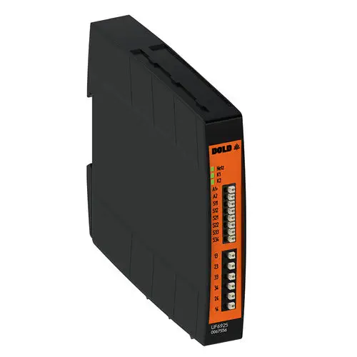
The DOLD UF 6925 is an ultra-compact emergency stop safety relay module from the SAFEMASTER series, designed to protect personnel and machinery by safely enabling or disabling safety circuits in applications with emergency stop buttons and safety gates. With its 2-channel redundant structure, it fulfills the highest safety requirements up to Category 4 / PL e (EN ISO 13849-1) and SIL 3 (IEC 61508/62061), making it suitable for demanding industrial safety applications including furnace installations according to EN 50156-1.
Ultra-Slim Design for Space-Saving Installation
The UF 6925 is only 17.5 mm wide, making it one of the most compact safety relays on the market. This ultra-slim form factor reduces space requirements in control cabinets by more than 20% compared to standard safety modules. The device snaps easily onto DIN rails (EN 60715) and features front-side push-in cage clamp terminals for time-saving, tool-free wiring, simplifying installation and maintenance.
Highest Safety Integrity with Forcibly Guided Contacts
The UF 6925 utilizes forcibly guided relay contacts in compliance with EN 60947-5-1, ensuring fail-safe operation. The UF 6925.03 variant provides 3 normally open (NO) safety contacts, while the UF 6925.22 variant offers 2 NO safety contacts and 1 normally closed (NC) monitoring contact. All safety contacts are forcibly guided, meaning that if a contact welds, the safety function is reliably interrupted. Switching capacity: AC-15: 3A (NO) / 1A (NC) at 230V; DC-13: 2A at 24V (both NO and NC).
2-Channel Redundant Operation
The device operates with a 2-channel redundant structure (dual-channel). This architecture ensures that a single fault does not lead to loss of the safety function, providing the highest level of safety integrity for critical applications. The redundant structure is essential for achieving Category 4 / PL e and SIL 3 certifications.
Flexible Configuration for Diverse Applications
Two DIP switches on the back of the device allow easy configuration without additional tools:
- Switch S1 (Cross Fault Detection): Enables or disables cross-fault monitoring in the emergency stop loop or safety gate circuit.
- Switch S2 (Start Mode): Selects between manual restart (requires a connected start button) and automatic restart. For manual start mode, a start button is connected to terminals S33-S34; for automatic start mode, terminals S33-S34 must be bridged.
The device also includes line fault detection on the start button. If a line fault (short circuit) occurs on the start button, the output contacts will not close, ensuring safe operation.
Wide Voltage Range for Versatile Applications
The UF 6925 supports a wide input voltage range of DC 8...36 V, making it insensitive to voltage fluctuations such as those occurring when battery-powered loads are switched on. This wide range allows the device to be used in a variety of machine and plant engineering applications as well as in mobile applications.
Clear LED Status Indication
Three LED indicators provide clear status information at a glance: LED "Power" (Netz) for supply voltage status, LED "K1" for channel 1 status, and LED "K2" for channel 2 status. This simplifies commissioning, troubleshooting, and ongoing maintenance.
Technical Specifications Summary
- Standards Compliance: EN ISO 13849-1, IEC 61508, IEC 62061, EN 50156-1, EN 61511, UL 60947-1, UL 60947-5-1
- Performance Level (EN ISO 13849-1): PL e / Category 4
- Safety Integrity Level (IEC/EN 61508/62061): SIL 3 / SIL CL 3
- Application: Emergency stop, safety gates, furnace installations, mobile applications
- Contact Variants: UF 6925.03 (3 NO safety contacts), UF 6925.22 (2 NO + 1 NC)
- Contact Type: Forcibly guided relay contacts
- Operating Frequency (max): 1,200 switching cycles per hour
- Short-Circuit Protection: Max. fuse rating 8 A gL (IEC/EN 60947-5-1), line circuit breaker B 6 A
- Overvoltage Protection: Internal VDR (voltage-dependent resistor)
- Short-Circuit Protection: Internal PTC thermistor
- Clearance and Creepage Distances: Rated impulse voltage 4 kV / pollution degree 2 (IEC 60664-1)
- EMC: IEC/EN 61326-3-1, limit value class B (EN 55011)
- Vibration Resistance: Designed for industrial conditions
- Climate Resistance: Suitable for -25°C to +55°C operation
- Terminal Designation: A1+, A2 (supply), S11, S21 (input channel 1), S12, S22 (input channel 2), S33, S34 (start circuit), 13,14,23,24,33,34 (output contacts), 31,32 (NC monitoring contact)
- Altitude: < 2,000 m
Applications
The DOLD UF 6925 is ideal for a wide range of safety applications, including emergency stop monitoring for industrial machinery, safety gate and guard door monitoring, furnace safety circuits (EN 50156-1), mobile equipment safety systems (with DC 8-36V wide voltage range), and general machine safety systems requiring Category 4 / PL e or SIL 3 safety integrity.
Resources & Documentation
DOLD UF 6925 Emergency Stop Safety Relay with 3 NO Contacts, PL e / SIL 3, 17.5 mm Width
Product Specifications
- Manufacturer
- DOLD
- Part Number
- UF 6925
- Product Type
- Safety Relay
- Safety Level (EN ISO 13849-1)
- PL e / Category 4
- Safety Level (IEC/EN 62061)
- SIL CL 3
- Safety Level (IEC/EN 61508/61511)
- SIL 3
- Output Contacts
- 3 NO (UF 6925.03) or 2 NO + 1 NC (UF 6925.22), forcibly guided
- Contact Switching Capacity (AC-15)
- 3 A @ 230 V (NO), 1 A @ 230 V (NC)
- Contact Switching Capacity (DC-13)
- 2 A @ 24 V (NO/NC)
- Thermal Current Ith
- Max. 8 A
- Supply Voltage
- DC 8...36 V (wide range)
- Power Consumption
- < 1.6 W (DC 24 V), < 2.2 W (DC 8...36 V)
- Operating Temperature
- -25°C to +55°C
- Storage Temperature
- -25°C to +85°C
- Protection Rating
- IP20
- Dimensions (W × H × D)
- 17.5 × 110 × 120 mm
- Weight
- Approx. 300 g
- Mounting
- DIN rail (EN 60715)
- Electrical Connection
- Front-side push-in cage clamp terminals
- Mechanical Life
- > 40 × 10⁶ operations
- Electrical Life
- > 1.0 × 10⁵ cycles (AC 230 V, 8 A, cos φ=1)
- Certifications
- UL, CE
Resources & Documentation
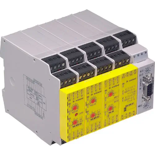
WIELAND ELECTRIC safe RELAY series
22.5mm compact, universal safety functions
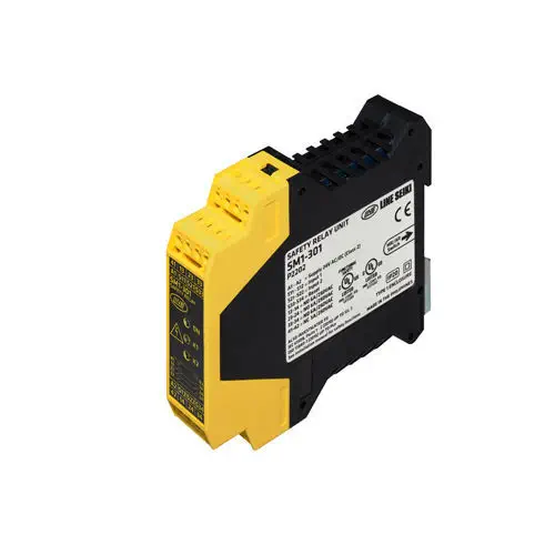
Line Seiki Co., Ltd. SM1-301
Dual-channel, 23mm ultra-compact
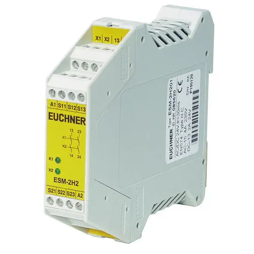
EUCHNER GmbH + Co. KG ESM-2H201
2 NO contacts, 0.5s synchro, short circuit/earth fault monitoring
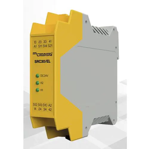
motrona SRC30/EL
3 safe contacts, 1/2-channel, OSSD support
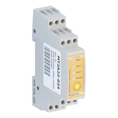
Comepi srl MT2A22-024
OSSD outputs, potential-free
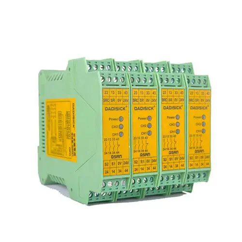
DADI ELECTRONIC TECHNOLOGY CO.,LTD. QSRN
Force-guided contacts, NPN/PNP compatible
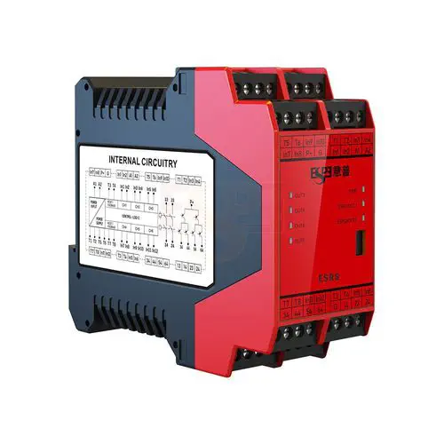
Shenzhen ESPE Technology Co., LTD ESRS-2A1B-E
Dual channel input, self-diagnosis, DIN rail mount
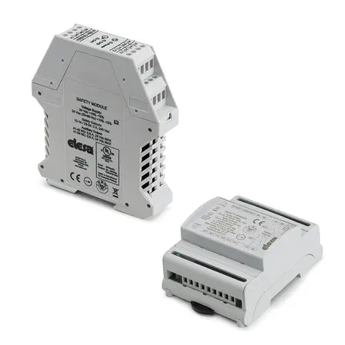
ELESA CN-SFT
Dual-channel, 2 NO safety outputs