The datasheet says "active barrier, loop-powered, HART transparent" — and the question is whether that combination works for your hazardous-area 4-20 mA loop or whether you need a different protection topology entirely. The E+H RN42 is a single-channel active barrier that takes its operating power from the 4-20 mA loop itself — no separate 24 VDC power supply required — while passing HART communication signals transparently through the isolation barrier. This makes it a drop-in protection device for simple loops. But the choice between active and passive barrier technology has implications for loop voltage budget, channel density, and diagnostic capability that a one-line datasheet bullet doesn't explain.
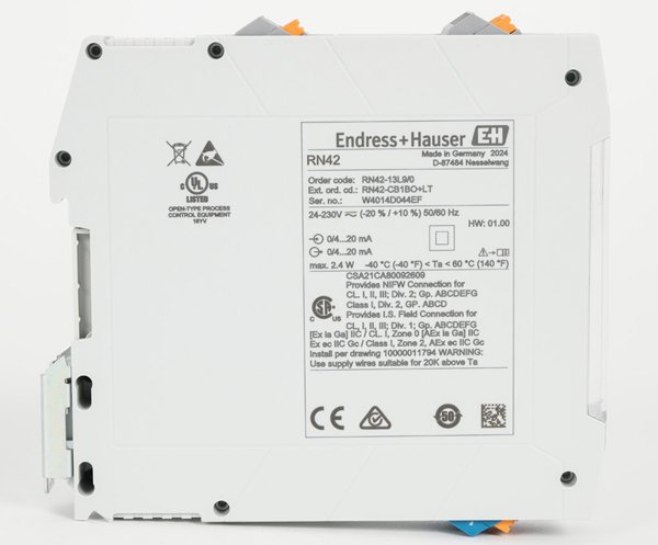
The RN42 belongs to a family of Endress+Hauser intrinsic safety barriers designed for DIN-rail mounting in the safe-area cabinet. It operates on the "active barrier" principle: the electronics are powered by the loop current flowing through the device, and the isolation between the hazardous-area (Ex) side and the safe-area (non-Ex) side is galvanic — typically 375 V peak — using a transformer-coupled DC-DC stage. A passive (zener) barrier, by contrast, relies on Zener diodes and a fuse to shunt fault energy to ground, requiring a dedicated high-integrity earth connection and consuming voltage headroom through the series current-limiting resistor. The active topology gives the RN42 three advantages over a passive zener barrier: lower loop voltage drop (typically 2.5 V vs. 5–7 V for a zener barrier), no requirement for an intrinsically safe earth connection, and HART signal pass-through with minimal attenuation — the RN42 is fully transparent to the 1200 Hz and 2200 Hz HART tones superimposed on the 4-20 mA analog signal.
RN42 vs. RN22: Single-Channel vs. Dual-Channel Decision
Endress+Hauser offers two active barriers in this series. The choice depends on whether you need one loop or two:
- E+H RN42
- Single-channel. Loop-powered (no auxiliary 24 VDC). HART transparent. 12.5 mm wide — 80 loops fit in a 1-meter DIN rail. The single-channel form factor means a failure on one loop does not affect any other loop, and you replace barriers one at a time without disturbing adjacent channels. Best for distributed I/O where each 4-20 mA transmitter gets its own barrier immediately adjacent to the PLC or DCS analog input card.
- E+H RN22
- Dual-channel. Also loop-powered and HART transparent. Same 12.5 mm width — the second channel is stacked inside the same housing, so you get two loops in the space of one RN42. The per-channel cost is roughly 40% lower, but both channels share a common power bus derived from the loop currents — a short-circuit on Channel 1 can pull down Channel 2 momentarily. Best for high-density installations where cabinet space is the binding constraint and loop independence at the barrier level is not required by the safety case.
The RN42 and RN22 are both HART transparent, but "transparent" does not mean "amplified." The HART signal passes through the galvanic isolation stage with approximately 1 dB of attenuation (roughly 10% amplitude loss). If your loop already has marginal HART signal levels — for example, a transmitter at the far end of a 3-kilometer cable run with 250 ohms loop resistance — the additional attenuation from the barrier may drop the HART signal below the detection threshold of the handheld communicator. In that scenario, test the HART signal level at the safe-area side of the RN42 before concluding the transmitter or communicator is faulty.
Loop Voltage Budget: Why the 2.5 V Drop Matters
Every device in a 4-20 mA loop consumes a share of the supply voltage. A typical loop uses a 24 VDC supply. The transmitter requires a minimum of 10–12 V at its terminals to operate. The wiring resistance (supply and return conductors) drops additional voltage proportional to the cable length and gauge. The barrier drops its own operating voltage. What remains is headroom.
With an RN42 active barrier (2.5 V drop), a loop with 500 meters of 18 AWG cable (approximately 10 ohms, or 0.2 V drop at 20 mA) and a transmitter requiring 12 V at its terminals leaves 24 − 12 − 2.5 − 0.2 = 9.3 V of headroom — which is comfortable. Replace the RN42 with a typical 300-ohm passive zener barrier (6 V drop at 20 mA) and the headroom shrinks to 24 − 12 − 6 − 0.2 = 5.8 V — still functional but sensitive to supply droop or degradation in cable connections over time. For loops powered by a 24 V supply at the long end of a cable run, the RN42's lower voltage drop is not a performance feature — it's the margin that keeps the loop working five years later when connector resistance has crept up and the power supply output has sagged 0.5 V.
When should I use an active barrier instead of a passive zener barrier?
Choose an active barrier like the RN42 when any of these conditions apply: (1) the loop voltage budget is tight — if the total loop resistance (transmitter minimum voltage + cable drop + barrier drop + sense resistor) exceeds 80% of the supply voltage, the 2–3 V saved by an active barrier is decisive; (2) the installation has no high-integrity intrinsically safe earth available — zener barriers require a dedicated IS ground with less than 1 ohm resistance to the plant earth grid, and if this ground is not verifiable, the barrier's fault-shunt protection is compromised; (3) you need HART transparency without a separate HART multiplexer — active barriers typically pass HART with minimal attenuation, while zener barriers require careful impedance matching to avoid attenuating the HART tones; (4) you are adding a single loop to an existing cabinet and do not want to run a separate 24 VDC supply — the RN42's loop-powered design eliminates one power distribution terminal block and its associated documentation burden.
Does the RN42 work with SIL-rated safety loops?
The RN42 carries an Ex rating (ATEX, IECEx) for intrinsic safety but does not carry a SIL capability rating itself. For SIL-rated safety instrumented functions, the entire loop must be assessed per IEC 61511, and the barrier's contribution to the probability of failure on demand (PFD) must be accounted for. If your safety function requires SIL 2 or SIL 3, consider a barrier with published PFD values and systematic capability (SC) ratings — typically found in the MTL or Pepperl+Fuchs SIL-rated barrier lines — rather than the general-purpose RN42. The RN42 can still be used in a SIL loop if the safety assessment credits it as a simple galvanic isolator with a documented failure mode (the device fails to a de-energized/open-circuit state) and the overall PFD budget allows for its contribution. Consult the IECEx certificate and the Endress+Hauser functional safety manual for the specific revision of the RN42 being installed — do not assume SIL applicability from the Ex certificate alone.
How do I test a loop through the RN42 without breaking the hazardous-area wiring?
The RN42 does not include built-in test terminals for inserting a milliammeter into the loop without disconnecting wires — a deliberate design tradeoff to keep the 12.5 mm width. To measure loop current without breaking the Ex-side circuit, use the safe-area side: connect a calibrated milliammeter in series with the RN42's non-Ex output terminals. This measures the same 4-20 mA current that reaches the PLC or DCS analog input card, and it verifies the entire signal path through the barrier. For HART diagnostics, connect the HART communicator across the safe-area terminals of the RN42 — the HART signal is present on the non-Ex side, and you can read transmitter parameters without opening the Ex-side junction box. For troubleshooting a loop where the RN42 itself is suspected as the fault, bridge around the barrier with a passive zener barrier like the MTL7700 — if the loop works with a different barrier, the RN42 is the problem. Alternatively, the E+H RLN22 NAMUR isolating amplifier provides a different topology (separately powered, relay output for alarm contact) if the loop-powered architecture of the RN42 does not fit the application.